The Floor
- army30th
- Apr 29, 2025
- 3 min read
Updated: Aug 12, 2025
A major component of the body is without a doubt, the floor. It is made of up 5 major pieces, those being: 2 sills, 2 mid-body cross members, and 1 rear cross member. The out lying pieces are the main floor board, the middle floor (under the gas tank), gas tank shut off board and the rear floor board. The rear floor is made of two boards for the passenger side and a battery access for the driver's side.

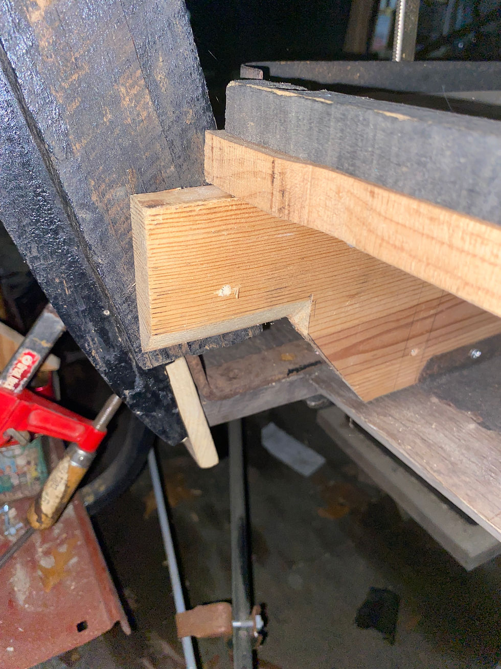
Here we see the main sills and the placement for the front cross member. This piece, according to the remaining original sill section, should be 4.5 inches in width. The piece that was recreated was not the correct size, so a replacement was made. The 4.5 dimension was determined by the mortise hole on the original remaining sill piece. The sills in this picture were fabricated by a previous owner and had to be fixed in order to fit the frame and maintain a 2 3/4 inch distance from the frame rails. The PILLAR COUPE notch also had to be adjusted because it was cut too long.

Here, we can see the placement of the reproduction floorboard by John Anderson. The current mortise hole in this piece is too short to allow for the 4.5 placement of the cross member. You can also see the inlet for the HINGE PILLAR upright bracket in the driver's side sill, but there isn't one in the passenger side. That will be corrected once it's placement is finalized. The blue tape denotes the addition of a piece of wood to compensate for the incorrect notching for the PILLAR COUPE.

We can see here that there are wooden dowel sections placed in bolt holes. This will be to hide additional holes that were drilled in the wrong place. The original sill's holes do not line up exactly with the holes currently drilled in the sills, so some adjustment/acceptance of the holes will be necessary. I am under the assumption that the sills are NOT mirror images of each other in the original build like I assumed they would be. The mounting angle brackets should be fixed in such a way as the body can be lifted off the frame in one single piece. or the boards attached to them can be removed if necessary.

This photo shows the placement of the PILLAR COUPE mounting bracket. It should be mounted with the bolt head up, but I elected to bolt it up this way instead. I might change it later, I haven't decided yet. The floorboard riser has a cutout to access this bolt for body removal. The PILLAR COUPE must be assembled first, and then the riser, because you cannot access the screws to the bracket otherwise.


Comments